Additive Build Advisor

A compact, readable design-to-inspection digital thread for additive
manufacturing. It takes a part geometry (STL), decides how to build it, simulates
the build, predicts distortion with a finite-element solve, checks whether the
part can actually be made and measured, and ends with a single auditable record
carrying an explicit release decision — release_to_build,
needs_engineering_review, or redesign_required.
Why I built it
I wanted a runnable artifact for the front half of a digital thread — design intent turning into a build decision — grounded in real additive-manufacturing physics rather than a black-box model. It hands off to a companion runtime-monitoring twin, so the two together span design → build → monitor. The geometry kernel, STL parser, voxelizer, orientation search, build simulation and the FEA solver are written from first principles on NumPy — no CAD kernel, no FEM package — so every engineering decision is legible and defensible.
How it works
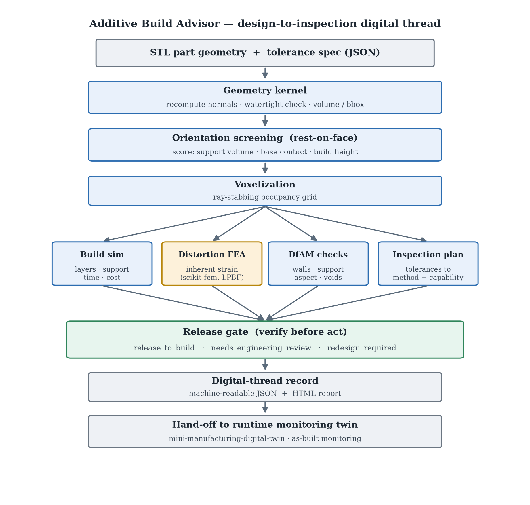
The pipeline reads top to bottom:
- Geometry kernel — parse the STL, recompute facet normals from winding, and verify the mesh is watertight before trusting it. The voxel volume is cross-checked against the analytic mesh volume on every run.
- Orientation screening — generate “rest on a flat face” candidates (the part’s own flat faces plus the bounding-box directions) and score each on actual support volume, base-contact area, and build height. No degenerate tilts — the part sits on a real face.
- Voxelization — a ray-stabbing occupancy grid turns the triangle soup into a solid model that the simulation, FEA, and DfAM checks all share.
- Three analyses + inspection run on that model: a build simulation (layers, support, time, cost), the distortion FEA, DfAM checks (thin walls, support burden, aspect ratio, trapped powder/resin), and an inspection plan derived from the part’s tolerances with an as-built process-capability check.
- Release gate — the advisor never silently approves a build. It releases, asks for engineering review, or blocks for redesign, with the specific reasons and blocking findings attached (verify-before-act).
- Digital-thread record — a machine-readable JSON + HTML report that hands off to the runtime monitoring twin.
Distortion FEA — the inherent-strain method
Distortion is predicted with a genuine finite-element solve. Each occupied voxel
becomes an 8-node hexahedral element; the build’s thermal shrinkage is modeled as
a uniform eigenstrain; the base is clamped to the plate; and equilibrium
K u = f is solved matrix-free with a preconditioned conjugate gradient. This is
the inherent-strain method — the accepted part-scale approach for metal
laser powder-bed fusion (LPBF), used by tools like Autodesk Netfabb and ANSYS
Additive, and the recognized validation artifact is the NIST AM-Bench 2018
cantilever/bridge.
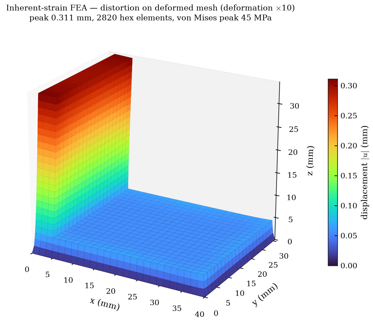
Deformed element mesh (exaggerated, contour-colored by displacement) — near zero at the clamped base, rising toward the free corners: the corner-lift that drives real additive distortion.
I’m precise about what the number is. The model holds the part bonded to the plate, so it reports the on-plate distortion — a relative warpage screen. It is not the post-release deflection NIST measures after cutting the part free (~1–1.3 mm for the IN625 cantilever); reproducing that needs a release step and a calibrated anisotropic inherent strain, which I list as the next step. I’d rather state that than fudge the match.
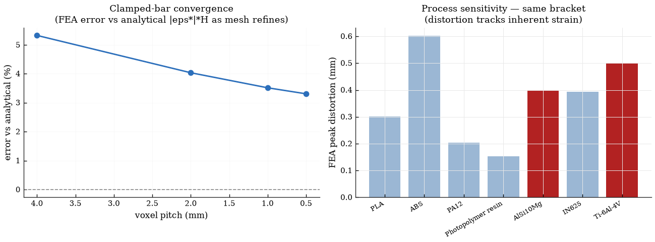
Validating the solver
I validated the FEA against the analytical clamped-bar solution (top displacement = |eigenstrain| × height): it converges under mesh refinement, and the predicted distortion is linear in eigenstrain and independent of Young’s modulus — exactly what linear elasticity requires for an eigenstrain-only load.
A lesson worth telling
My first orientation scorer used overhang facet area and happily chose a 45° edge-balanced tilt — mathematically zero overhang, physically absurd (no flat base, huge support). The fix was to score what actually costs money: support volume and base contact from a real voxelization. A metric that is cheap to game is the wrong metric.
Code
The full project, technical report, FEA validation, and tests are on GitHub.